Updated 6 May 2024 MW
This board includes the following features:
- VFO – from a few kilohertz above the LO frequency (Sat 8MHz) to 150MHZ. The Si5351 device has been used. Against any criticism is has proved to be an excellent device, stable and quiet in nature. Two of these Si5351 devices are used, one exclusively for the VFO and the other for BFO / CIO / TXO. A TCXO can be fitted is desired.
- Double-balanced mixer. The SMD ADE-1 works very well or an older SBL-1 can be used.
- Front-end diplexer filter
- First Xtal filter / delay and Noise blanker (Woodpecker, static-crash, electric fence etc)
- Variable IF to suit your Crystals! Different IF Frequencies can be chosen using the Function rotary control. The current design works on either 8, 9 or 10.7MHz. These are the base frequencies and a software feature allows the IF to be varied away from any one of these base frequencies. For example, you can buy bags of 10 / 100 XTALS from a supplier and then match 8 of them together in frequency and for minimum loss, and these become the First filter (2) and SSB (6). Next you can select another 5 XTALS on the same frequency, or close by frequency, and these become the CW XTAL filter.
- All Crystals needed can be sourced from hampiradio.com or SSB & CW Crystal filters can be sources from Spectrum Communication who sell them for 9, at a reasonable price and they work well. You can source and select your own (note above).
- Front end and triple Intermediate Frequency variable gain Amplifiers (AGC) using dual gate MOSFETs BF998 devices.
- Notch filter
- Balanced Detector
- Four stage Audio filter (2 SSB and 2 CW stage). This cleans up audio hiss very well and narrows the audio bandwidth.
- Audio amplifier.
- Automatic Gain Control AGC.
- Full break-in CW RX/TX switching and muting.
- CW Keyer (stereo jack and software keying for straight key or paddle)
- TX VOGAD microphone amplifier / compression
- TX Audio filtering
- TX Modulator
- TX amplifier stages & RF TX Output amplifier
- Other ancillary functions
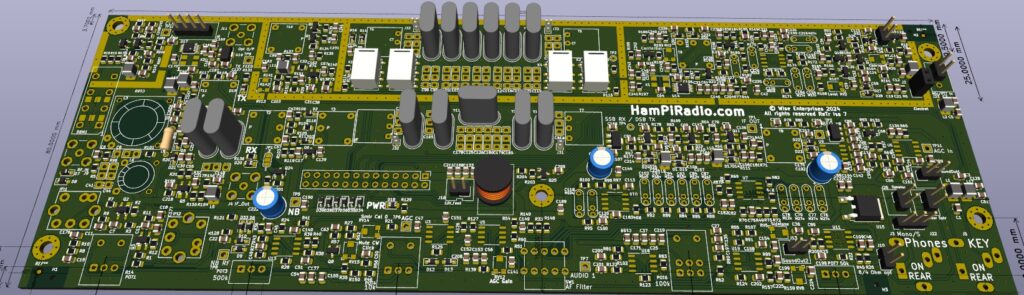
- This board has recently been converted to SMD for the majority of the components as the parts count was approaching 500, which is complex and the chances of construction errors / dry joints etc became too high. This means the project is drastically simplified. See the photo below and note the SMD parts and the as yet on this photo unmounted hand fit parts.
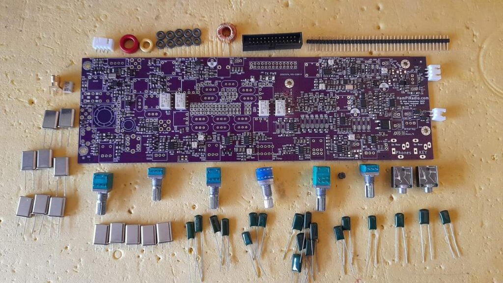
The photos below show part of the Radio board (An earlier prototype).
Construction
- IF Frequency. 8, 9, or 10.7mHz. 8 or 9mHz is recommended. Other base IF frequencies are easily possible with a requested firmware change.
- Crystal CW Filter / SSB Filters. CW filter can be omitted, but if you are a seasoned CW Op you will want it even thought the Audio Filter is adequate.
- Various areas were left unmasked giving provision for screening, but screens were (fortunately) found to be unnecessary.
- Choose and fit the mixer. Either a ADE-1 or SBL-1
Diplexer
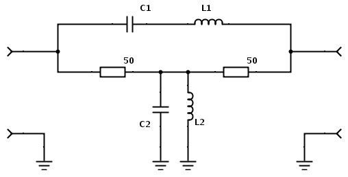
| Diplexer | 8MHz IF | 9MHz IF | 10.7MHz IF |
| C8 | 39pF | 70pF | 50pF |
| L3 | T50-6(Red) 40turns (16mm/turn 660mm) 9.9uH | T50-6(Yellow) 30 Turns (500mm) 4.4uH | T50-6(Yellow) 30 Turns (500mm) 4.4uH |
| C41 & C44 | 3900pF (or 1nF?) | 1640pF (808+820) | 1262pF (820+470) |
| L6 | T37-6(Yellow) 9 or 10 turns (140mm) 0.1uH | T37-6(Yellow) 7 turns (100mm) | T37-6(Yellow) 7 turns |
For 8mHz calculator at https://www.changpuak.ch/electronics/calc_16a.php used. 1nf in practice though…
L3 Yellow T50-6 30turns 0.3mm (15mm/t 500mm) 4.4uH
L6 Yellow T37-6 7turns 0.5mm (12mm/100mm) 0.19uH
Series reactance = 5xZ = 5×50 = 250R
Shunt reactance = Z/5 = 50/5 = 10R
Notes:
If you have an an inductance meter measure the inductance of these coils and squeeze or spread out the turns to get the correct measurement. There is provision on the PCB to tie down these coils with a length of non conductive thread / Sturdi-Lace.
When winding coils on ferrite be careful to not scratch off the enamel coating. The ferrite can have sharp edge. While it does not matter if the ferrite is in contact with the actual copper as it is an insulator, it does matter a lot if the windings are shorted together. Shorted-turns will effect performance negatively, and are very hard to find.
Ferrite Transformers
| Core | Primary turns | Secondary turns | Wire | Length | |
| T1 | HP-43 | 10 | 10 | 0.3 (28SWG) | 100+100 twist together by hand then Bifilar wound |
| T2 | BN62-2402 | 12 | 2ct (1+1) | 0.2 (38SWG) | 250/40+40 |
| T3 | BN62-2402 | 4ct (2+2) | 12 | 0.2 (38SWG) | 250/60+60 |
| T4, 5 | HP-43 | 7 | 7ct (7+7 ?? MW) | 0.3 | 80/80 twist together by hand then Bifilar wound80/80 |
| T6, 7 | HP-43 | 11 | 11 (?? MW) | 0.3 | 80/80 twist together by hand then Bifilar wound80/80 |
| T8 | HP-43 | 6 (37uH) | 16 (195uH) | 0.3 | 85/130 |
| T9 | HP-43 | 11 | 5 | 0.3 | 110/60 |
| T10 | HP-43 | 11 | 5 | 0.3 | 110/60 |
Notes:
- The HP-43 ferrites measure just 6x2mm and are available from hampiradio.com. FT37-43 ferrites will also work but are larger and will be more cumbersome to fit. They are also expensive.
Noise Blanker
IFT1 / IFT2 The available from hampiradio.com are marked 3245 and are custom manufactured. They need an external 47pf capacitor which is already mounted on the PCB. Two TOKO4520 (4.4uH) or equivalent 10mm IF transformers can be used. The TOKO4520 has an internal 51pF capacitor fitted and if used the external 47pF capacitors must be removed from the PCB.
When testing put an oscilloscope on TP8. Apply a -20dBm signal on the antenna (or input) and tune the two cores for maximum output. This is a basic two stage narrow band RF amplifier which amplifies the RF input to trigger such as static crashes and Woodpecker signals. The filter cuts out interferences above about -50dBm to trigger the blanker, and must be larger than the desired signal. Filter F1/F8 is a delay so that the noise blanker is activated by Q6 before the noise arrives at the blanker.
Text below is under construction / correction… MW
Alignment & Selection of Software Options
- Connect a 26way Ribbon cable from the CPU board.
- Connect a 4 way shielded cable from the CPU board connector marked VFO to the similar connector by on the top LHS corner by the VCO Si5351.
- Connect power to the PCB. This is done by putting 13.8V to EITHER the CPU or Radio board using the 2-Pin connector J16. Pin 1 is -ve and Pin 2 is +ve
- Press the Function button a few times until (MW ADD CORRECT TEXT FOR SELECTING SUB_OPTIONS) IF= is displayed. Rotate the Function control until the correct IF is selected, 8, 9 or 10.7, and then press the SET button. This saves the selection permanently to E2PROM. Remove and apply power to recall this IF.
- Using an oscilloscope check there is a 25MHz oscillator signal at the TCXO output and OSC input pin 2 of the Si5351.
- CALIBRATE VFO. Use a frequency counter and measure the VFO signal. This can be done Pin 1 of J1, or at various points around Q1.
- Ensure the VFO on the display of the CPU is set to 14.200.000MHZ and press the LOCK button.
- Ensure MODE is set to USB.
- Press the Function button a few times until CalVFO is displayed. Now turn the function control one way or the other until the Frequency Counter displays the correct IF frequency. This will be 23.201.500 MHZ for a 9MHZ IF, and 24.901.500 for a 10.7MHZ IF. When it is spot on, press the SET button. This will save the calibration in E2PROM so that at power up the calibration is remembered permanently. It should never (but can) need to be redone.
- CALIBRATE BFO. Use a frequency counter and measure the BFO signal. This can be done Pin 1 of J7. Ensure the MODE is set to USB.
- Press the Function button until CalBFO is displayed. Now turn the function control one way or the other until the Frequency Counter displays the correct BFO frequency. This will be 9.001.500 MHZ for a 9MHZ IF, and 10.701.500 for a 10.7MHZ IF. When it is spot on, press the SET button. This will save the calibration in E2PROM so that at power up the calibration is remembered permanently. It should never (but can) need to be redone.
More to follow…
![]()