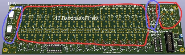
The bandpass filter board is in some regards a simple thing, but don’t be fooled. It is a central and extremely important part of any radio design. See it as a funnel, two directional for RX and TX. If there are any obstructions in this tunnel it will reflect significantly on the performance, receive and transmit. When testing or finding one particular band, say, is not working well (low output power, or poor performance on receive), suspect the BPF first!, and re-test it. For this reason it is worth a lot of effort to get this board right, and indeed there have been a few prototypes and a lot of time spent in perfecting this board.
- 16 BandPass filters:
- 1800 & 630 Meters LF Bands 1 & 2
- 160 through 10 Meters HF Bands 3 – 13
- 6, 4 & 2Meters VHF Bands (Not all countries are allowed the 4M band) 14, 15 & 16
- Each selected with 4 bit parallel TTL level logic (0000 – 1111 Binary)
- Switching can be done with EITHER 16 PIN diode switches OR the option to use very small OMRON G6K relays. A choice of a small performance gain vs cost.
- If this BPF board for a non HamPi Radio project, and BCD selection not wanted, band selection can be done by fitting ribbon cable or wires for individual band selections. This is simply done by grounding any BPF to select it.
- A LED indicator is there for each BPF to indicates which Band is selected. It is extremely helpful (and less frustrating) to be tuning the correct coil!
- 14dB or 18dB Attenuator (or any other, depending on the 3 resistors fitted)
- 18dB Preamplifier (remember one S unit is 6db below S9, and 10dB above S9)
- 2 x notch filters for tuning out Local Oscillator leakage. Very important of TX.
- 2 x Relays for selection of external LF and VHF modules
Understanding Band Pass Filter and setup in a nutshell
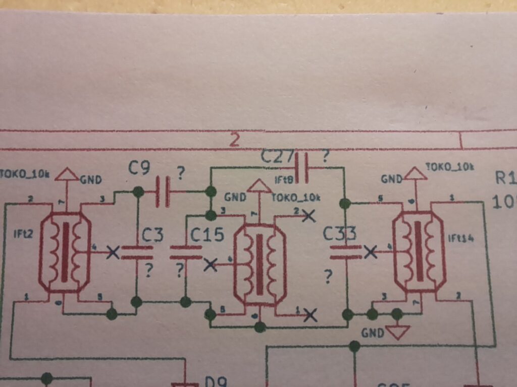
Have a look at the picture above. There are three tuned circuit stages to this filter. Each stage has a transformer and capacitor that resonate together. In this case IFT2 & C3, IFT8 & C15, and IFT14 & C33. The two other capacitors C9 & C27 link, or couple the stages together. This is how each stage work, and what to aim for:
- Aim to have all capacitors as low in value as possible, so as to achieve the best performance.
- If the capacitance is too low, tuning DOWN to to the desired frequency will not e possible, and a higher value cap will be needed. If the capacitance is too high, performance will suffer, shown by like too much loss.
- Coupling Capacitors C9 & C27 set the bandwidth of the circuit. The aim is to have the lowest overall loss, while also having a wide enough, but not too wide bandwidth. The larger the capacitance the wider the bandwidth, but the loss lower loss. The lower the capacitance the sharper the notch and narrower bandwidth, but then loss will be higher covered. The aim again is to cover the particular band (Say 14.000 to 14.350mHz for 20 Meters) with a relatively flat top, and to see a sharp roll-off as the signal gets out of band. (see below)
- Resonance C3, C15 & C33 are the capacitors in parallel with the individual transformers. If the capacitance is too high there will be a triple peak and the pass-band will be too wide. If the capacitance is too small the circuit will not tune DOWN to the desired frequency, and the ferrite slug in the transformer will be out of the top or bottom of the core.
- As a rule of thumb, if the ferrite slug is close to the top of the core but not perturbing past the top this will be the best condition.
- In simple terms see the capacitors as slugging, or dampening the ferrite transformer. The higher the capacitance the more dampening. A bit like putting a finger on a piano string near the end. Too much pressure and the string cannot freely vibrate.
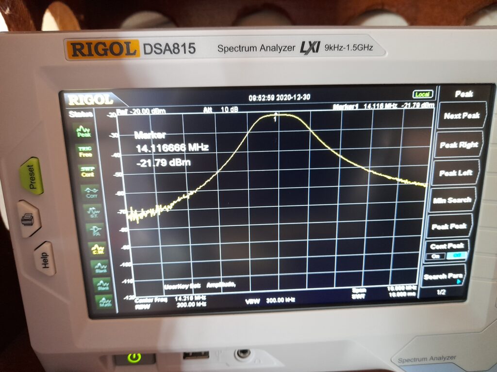
- See the image below. This is an example on 20 Metres and the loss here is 1.79dBm. Note that at 1mHz each side of the center frequency the filter has achieved a 10dB attenuation, and at around 1.5mHz it is -20dBm attenuation.
- Tune all three transformers to achieve the shape below. The centre transformer, IFT8, it will be seen to only changes the frequency and not the amplitude. The outer two transformers adjust the amplitude mostly, and not much change in frequency.
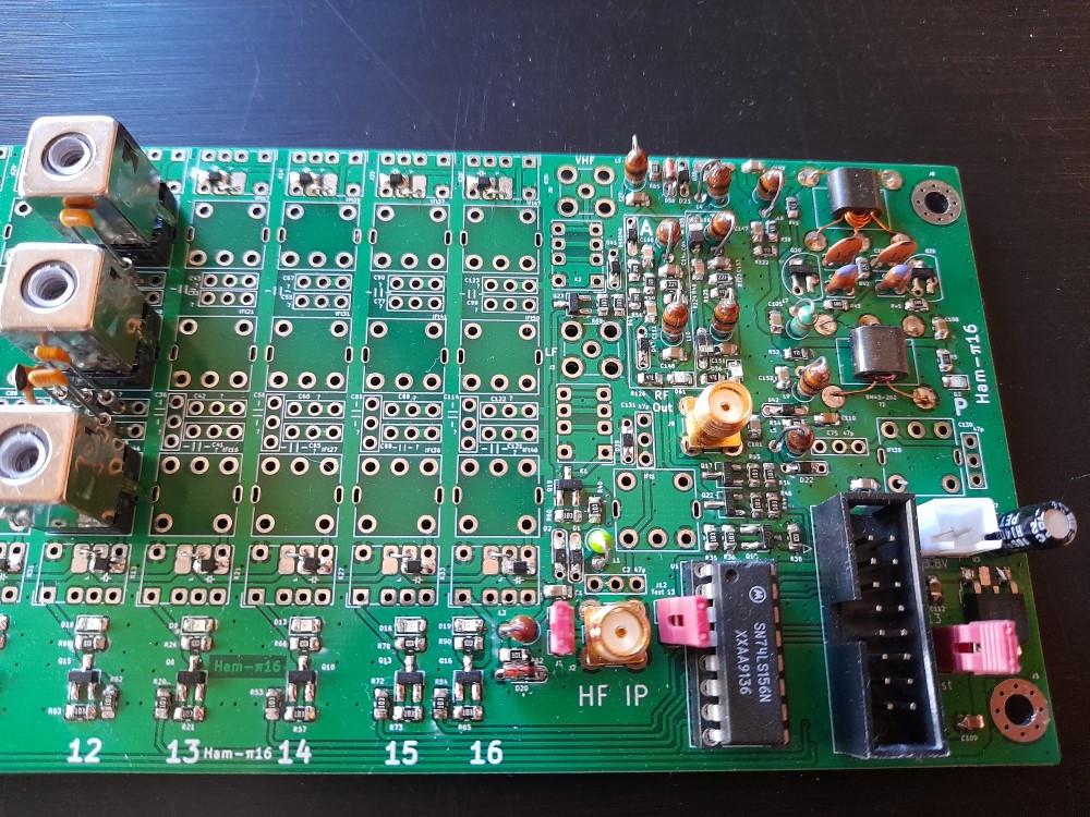
- It is desirable to have a Spectrum Analyser with a tracking generator option to do this. The one below does a splendid job, but costs around NZ$2500. If you do not have one or you have no access to one (another HAM?, Club), a NANO VNA will also do the job, and are much cheaper. It can be done with a signal generator and a good oscilloscope too monitoring the RF and noting the loss, peaking the sign wave.
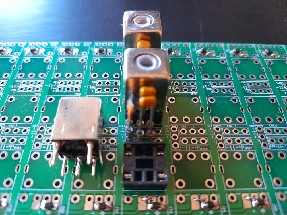
- For selecting parts and tuning use the band marked ’12’, and fit sockets for easy part substitution. This band is at present unused (11mtrs) and is covered by the 10m band 13. See picture below.
![]()