Updated 17 May 2025

Radio Board features:
- This is the most complicated board with over 600 components. Luckily, most of them are surface mounted and come mounted.
- VFO – from a few kilohertz above the LO frequency to 160MHZ. The Si5351 device has been used. Against some criticism is has proved to be an excellent device, stable and quiet in nature. Two of these Si5351 devices are used, one exclusively for the VFO and the other for BFO / CIO / TXO. A TCXO can be fitted if desired.
- Double-balanced mixer. The SMD ADE-1 works very well or an older SBL-1 can be used, or a homemade DBM can be fitted.
- Front-end diplexer filter at the LO.
- SSB and CW Crystal Filters.
- First Crystal wide filter / delay and Noise blanker (Woodpecker, static-crash, electric fence etc).
- Variable IF to suit your Crystal choice. Different IF Frequencies can be chosen in software using a function. The current design works on either 8, 9 or 10.7MHz. These are the base frequencies and a software feature allows the IF to be varied away from any one of these base frequencies. For example, qualities of cheap crystals can be purchased from a supplier and then 13 matched. For this design 2 are needed for the first filter/delay, 6 for the SSB filter and another 5 for the narrow CW filter. This CW filter is optional and need not be on exactly the same frequency. All Crystals can be purchased already matched from hampiradio.com.
- 4 stages of IF (Intermediate Frequency) amplification using variable gain AGC using dual gate MOSFET devices.
- Notch filter
- Four stage Audio filter (3 for SSB and 1 for CW). This filter cleans up audio hiss very well and narrows the audio bandwidth. This might seem like an over kill, having a CWA and Audio filter, but under harsh conditions is is useful to have one, or the other or both at hand.
- Audio amplifier.
- Automatic Gain Control AGC.
- Full break-in CW RX/TX switching and muting.
- CW Keyer. A stereo 3.5mm jack is fitted for a straight key or paddle to be fitted. (A future feature is to create software for the paddle)
- TX microphone compression, Audio filtering, Balanced Modulator, filtering and amplification
- Other ancillary functions
- This board has recently been converted to SMD for the majority of the components as the parts count is currently over 630. This means the project is drastically simplified. See the photo below and note the SMD parts and the as yet on this photo unmounted hand fit parts.
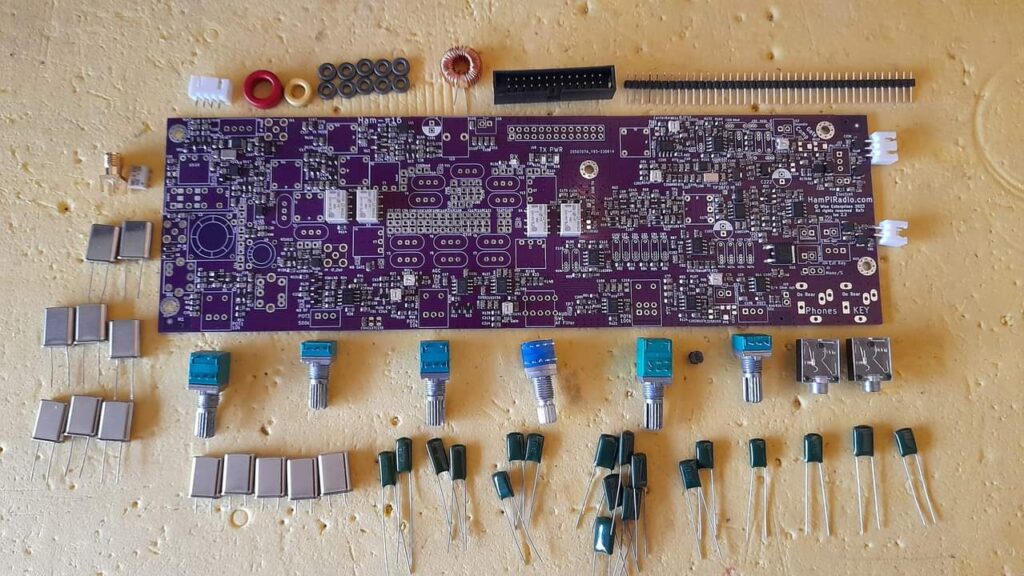
This photo shows part of the hand fitted parts on the Radio Board (An earlier issue PCB).
Component Selection and General Information
Construction
- Crystal SSB and CW Filters. The standard and fully tested HamPi Radio Board uses 8MHz IF Frequency filters and defines the IF Frequency. There is however provision in the firmware to select different IF frequency, either 8, 9, or 10.7MHz as a bass frequency. The IF frequency is then variable in software away from this base frequency as needed. Crystal filters are usually not exactly in 8MHz (or 9, or 10.7MHz). For this reason in the HamPiRadio has a variable IF feature where the IF can be changes to adjust the IF away from 8MHz to match the frequency of the crystals.
- Crystals will be available from this website which are already selected into matching sets. They can be soldered into the PCB and work as expected with no other capacitor changes needed.
- The calibration procedure for the actual frequency frequency is described in the setup section below.
- Crystal CW Filter. The CW filter is normally included, but can be omitted. If you are a seasoned CW Operator you will want it even thought the Audio Filter is adequate.
Radio Board – Hand fitted parts list
| Reference # | Quantity | Circuit Id. | Part | Description | Comment |
| 1 | 1 | DBM1 | Mixer | ADE-1 or SLB-1 | |
| 2 | 8 | Y1 – Y8 | Crystal | HC49-U | Pre-Filter/Delay and SSB Filter (8MHz Std) |
| 3 | 5 | Y9 – Y13 | Crystal | HC49-U | CW Filter (8MHz Std) |
| 4 | 2 | IFT1 & IFT2 | KACS4520 Toko | 10mm Ferrite Transformer | Or modified HP4356 |
| 5 | 1 | J19 | 26 way IDC Plug | Ribbon cable plug | Vertical |
| 6 | 1 | L12 | Choke | 5.5mm lead spacing | On 13.8V in. See notes |
| 7 | 3 | C190, 191, 222 | Electrolytic Caps 220uF | Radial_D6.3mm_P2.50mm | |
| 8 | 2 | T2 & T3 | BN43-2402 | Binocular Ferrite core | Noise Blanker |
| 9 | 7 | T1, T4 – T8, T10 | HP43 | Ferrite ring | Or FT38-43 See notes |
| 10 | 1 | L3 | Inductor Coil | T50-6(Red) | Diplexer |
| 11 | 1 | L6 | Inductor Coil | T37-6(Yellow) | Diplexer |
| 12 | 1 | J6 | Pin Header | 1x04_P2.54mm_Vertical | 4 pin for VFO |
| 13 | 1 | J23 | Pin Header | 1x03_P2.54mm_Vertical | 3 pin for Mic / PTT |
| 14 | 6 | J1, J2, J7, J13, J26, | Pin Header | 2x02_P2.54mm_Vertical | 2 pin for Electret, Sound in, Sound out 1 & 2, Speaker, Rear Speaker |
| 15 | 2 | J5 & J22 | Jack Skt | 3.5mm | Phones, CW Key |
| 16 | 1 | RV12 | Bourns 25 turns 3296W Trimpot | 50k lin | AGC Gain |
| 17 | 1 | RV14 | Bourns 25 turns 3296W Trimpot | 10k lin | S-Meter Zero |
| 18 | 1 | POT1 & POT4 | RK097NS | 10k lin + switch | Noise Blanker Gain |
| 19 | 1 | POT3 | RK097N | 500k lin | AGC Decay |
| 20 | 1 | POT6 | RK097NS | Dual 100k + switch | Notch Filter |
| 21 | 1 | POT7 | RK097N | 50k LOG | AF Gain (Volume) |
| 22 | 1 | SW1 | RS1010 | 5 position Rotary Switch | Audio Filter select |
| 23 | 2 | J4 & J9 | SMA Coax Socket | Straight. RF in/out & IF Out | |
| 24 | 16 | Caps (SSB Filter) | Ceramic Caps | 0805 or 1206 smd or THT | Must be C0G Ceramic |
| 25 | 11 | Caps (CW Filter) | Ceramic Caps | 0806 or 1206 smd or THT | Must be C0G Ceramic |
| 26 | 2 | C8 & C138 | Capacitor 33pf | 0806 or 1206 smd or THT | Diplexer. See text |
| 27 | 1 | C41 | Capacitor 2.2nF | 0806 or 1206 smd or THT | |
| 27 | 1 | C42 | Capacitor | 0806 or 1206 smd or THT | Not Fitted |
| Non Soldered Parts | Quantity | A 4 pin Mic plug, or more pins – a choice depending on the microphone used See text. | Description | Comment | |
| 1 | 5 | M3, 5mm Stand off | Board-Chassis spacer | Hex & Threaded | |
| 2 | 10 | M3 H5 | 5mm Screws | Hex or Pozidriv | |
| 3 | 1 | Ribon Cable | Ribbon cable 0.05″ pitch 26 way | 26 way with 2 row (13+13) Length 210mm | |
| 4 | 1 | Mini coax cable | Mini coax cable to BPF Board | SMA to SMA Length 210mm | |
| 5 | 1 | Mini coax cable | IF Output to rear panel or SDR Stick to USB | SMA to BNC OR SMA to SMA | Optional |
| 6 | 6 | Knobs | 6 mm Knurled Shaft Insert Diameter | for 15mm shaft length | Control knobs of your choice |
| 7 | 1 | Mic / PTT Lead | P3 3 way Pin Header lead socket to Mic cable | Chassis mounting Microphone Plug + 150mm ling using 2 core Audio Coax wire. | Ribbon Cable |
- If a full kit has been sourced from HamPiRadio then all parts mentioned below will be in the kit.
- Carefully inspect the board for damage and note any missing parts. Some parts are not fitted due to cost and it is much cheaper to hand fit them, other parts are intentionally fitted (nf on the circuit diagram).
- Do any suggested modifications next. If there are any, it is easiest to do these before adding the other parts.
- It is not necessary to fit pins in the Test Points, but this can be done as a preference. A oscilloscope fits in the PCB test point holes conveniently.
- Choose and fit the mixer. This can either be an ADE-1 (SMD) or SBL-1 (Through hole). Either perform equally well.
- If not already fitted, mount and solder all capacitors associated with the Crystal filters. There will be 13 crystals in all on this PCB. It is best to use COG type parts as they will be temperature stable. An example is: 50V 39pF C0G ±5% 0805 Multilayer Ceramic Capacitors. The footprint for these capacitors caters for both SMD and THT parts so through hole multi-layer ceramic leaded capacitors can be used rather than SMD parts if desired.
- Solder all of the 13 crystals. Provision is made on the Crystal PCB footprints to solder (GND) the Crystal cans. This is recommended when the Radio Board has been fully set up and tested, just in case a crystal has to be removed (Which is extremely unlikel). Note for the serious experimenter: It is possible to use SMD Crystals if you can find suitable ones (and are not resonators sold as crystals!). The footprints allow for mounting these on the reverse side (B) of the PCB.
- Solder all of the MYLAR Capacitors which are associated with the Receive Audio Filter and the Transmit Audio Filter. The values are all marked on the PCB in silk screen. The values begin with an ‘M’ indicating these tall green Mylar capacitors. Examples are M10n for 10nF or on these capacitors marked 103. In the RX Audio Filter section will be found these values: M27n for 27nF marked 273, M12n for 12nF marked 123, M15n for 15nF marked 153, M2n2 for 2.2nF marked 222, M22n for 22nF marked 223, M18n for 18nF marked 183, M1n5 for 1.5nF marked 152, M10 for 10nF marked 103. In the TX Audio Filter section will be found M27n for 27nF marked 273, M12n for 12nF marked 123, M6n8 for 6.8nf marked 682, and M2n2 or 2.2nF marked 222. The lead widths, space between the wires coming out of the bottom of these Mylar capacitors varies, and the PCB footprints cater for this. Choose one of the three holes and the one hole at the other end of the footprint to suit the lead width.
- Solder the 26 pin IDC Plug observing the orientation. Pin 1 is to the top right and the cut out groove goes towards the top of the board.
- Solder in these parts: White pin headers (1 x 4 pin J6, 1 x 3 pin J23, 4 x 2 pin J1, 13, 15, 26, )
- Continue reading below for construction and mounting of the inductors and transformers and the rest of the parts.
Inductors and ferrite transformers
The ferrite transformers need to be carefully constructed using the instructions following. It is worth taking time and patience to do this as fault finding incorrectly transformers or shorted turns (due to scratching of the enamel wire causing short circuits) is a nightmare. Enjoy the process…
Diplexer (Bridged Tee)

| Diplexer | 8MHz IF (The HamPiRadio standard) | 9MHz IF | 10.7MHz IF |
| C8 | 33pF | 70pF | 50pF |
| L3 0.32mm | 9.9uH T50-6(Red) 44 turns (16mm/turn 660mm) 0.3mm | 4.4uH T50-6(Yellow) 30 Turns (500mm) 0.3mm | 4.4uH T50-6(Yellow) 30 Turns (500mm) 0.3mm |
| C41 & C44 | 2200pf | 1640pF (820pf+820pf) | 1262pF (820pf+470pf) |
| L6 | 0.19uH T37-6(Yellow) 7 turns (100mm) 0.5mm | 0.19uH T37-6(Yellow) 7 turns (100mm) 0.5mm | 0.19uH T37-6(Yellow) 7 turns (100mm) 0.5mm |
| R96 & R101 | 51R & 51R | 51R & 51R | 51R & 51R |
The Diplexer needs to be designed / tuned to the centre of the IF Frequency. A diplexer is both a notch and a bandpass filter combined.
An article can be found here: https://www.qsl.net/g3oou/mixerterminations.html and a calculator here: https://www.changpuak.ch/electronics/calc_16a.php
To calculate: B = Bandwidth in Hz, Fs = Centre frequency in Hz, R = Impedance in Ohms (50R).
L3 = R / (2π x B)
L6 = (B x R) / (2π x Fs2)
C8 = B / (2π x Fs2 x R)
C41 / C44 = 1 / (2π x B x R)

Diplexer coils L3 and L6 on the Radio Board. Note the capacitors are already fitted.
Notes:
– If you have an an inductance meter measure the inductance of these coils and squeeze or spread out the turns to get the correct measurement.
– There is provision on the PCB to tie down these coils with a length of non conductive thread / Cable Lacing etc.
– When winding coils on ferrite be careful to not scratch off the enamel coating. The ferrite can have sharp edge. While it does not matter if the ferrite is in contact with the actual copper as it is an insulator, it does matter a lot if the windings are shorted together. Shorted-turns will effect performance negatively, and are very hard to find.
Ferrite Transformer Information
| Part | Core | Primary turns | Secondary turns | Wire | Length in mm |
| T1 | HP-43 Front End Amp | 16 | 7 | 0.3 (28SWG) | 150 + 75 |
| T2 | BN43-2402 Noise Blanker in | 12 | 2ct (1+1) | 0.2 (38SWG) | 240 primary, 40 + 40 secondary |
| T3 | BN43-2402 Noise Blanker out | 4ct (2+2) | 12 | 0.2 (38SWG) | 60 + 60 primary 250 secondary |
| T4, 5 | HP-43 SSB Filter in and out | 7 | 7 | 0.3 | 80 + 80 twist together by hand then Bifilar wound |
| T6, 7 | HP-43 CW Filter in and out (Optional) | 11 | 11 | 0.3 | 115 + 115 twist together by hand then Bifilar wound |
| T8 | HP-43 IF Amp out | 8 | 4+4 | 0.3 | 85/50+50 |
| BN | 0 | ||||
| T10 | HP-43 TX Buffer out | 12 | 3 | 0.3 | 120 + 40 |

Above: T1 (First IF). Wind the 16 Primary (P) turns around the core. Next wind the 7 Secondary (S) turns, these go over the top of the primary turns. Remember that 16 turns means the wire passes through the centre of the core 16 times, and when counted on the outside of the core there will be 15.

Above: T2 & T3 (Noise Blanker). These are similar in construction but T3 has more turns and is reversed. This description is for T2. From the sketches above:
1. Cut the length of enamelled copper wire for the Primary and wind onto the core. There are 12 turns. One turn is the wire passed through one hole AND back again through the other hole. Keep the turns somewhat tight and be careful to not scratch the wire on the ferrite.
2. (Note: on this sketch the primary is not shown). Cut the two pieces of wire for the secondary. Scratch off 5mm of enamel on one end of each wire, and twist together and solder. See the red and green wired in the diagram. Next pass the two free wire ends through the core at the opposite end from the Primary turns.
3. (Note: on this sketch the primary is not shown). Now pass the wires back through the core. This forms the 2 turns – Centre Tapped (CT). The only difference with T3 is it has 4 turns Centre Tapped, and so the 2 wires have to be passed through the ferrite core AND back again one more time. Things can get a little tight, but it is not too difficult with care. Use tweezers to push the wires through if needed, again being careful not to scratch the enamel. If needed use a small wooden tooth-pick and push it through a hole to gently move the wires aside.
4. Sketch 4 shows the completed T2. Cut the wires back to 15mm long and scratch off the enamel 5mm and tin.
6. The transformers can now be soldered onto the PCB.. Next, have a cuppa and congratulate yourself. This is probably the most fiddly part of the board!

Above: T5 (SSB Crystal Filter Matching). T6 is identical. From the sketches above:
- Cut two pieces of wire to length ans twist them together.
- Wind the twisted pare onto the ferrite core
- Separate the 4 ends. Cut the wires back to 15mm long and scratch off the enamel 5mm and tin.
- Use a multimeter on a low Ohms range (often the lowest range is 200Ohms and this is the one to select) or using a buzzer function. Identify the wires buzz out OK (If they all buzz you have shorted turns due to damages enamel, and will have to start from step one again!). Now, identify two odd the wire ends that so not buzz and are at OPPOSITE ends of the windings. See the sketch above, you are selecting one red and one blue wire. Twist together these ends where they were tinned and solder them together. For an extra check, the two free ends not soldered together should not buzz.
- These transformers can now be soldered onto the PCB…

Above: T6 (CW Crystal Filter Matching). T7 is identical to T6. For these two transformers follow the notes above for T4 & T5. The only difference is that these two use longer wire and have more turns. These transformers can now be soldered onto the PCB…

Above: T8 (IF Out to Product Detector in).
1. Wind this transformer Secondary (S) in a very similar way to T5 above, but note the end result as per the sketch and photo here. Twist and solder the two ends in the same way also.
2. Add the Primary (P) windings next and strip and tin the ends.
3. This transformer can now be soldered onto the PCB….

Above: T10 (TX RF). This is a simple transformer with a Primary and Secondary. Build and fit as per this picture.
Transformer Notes:
- The HP-43 ferrites used for the HamPiRadio. They are 6mm x 2mm with a 3mm aperture (hole). These can be ordered from AliExpress or supplied at hampiradio.com.
- One turn of enamelled copper wire is 8mm and 15mm is allowed for each tail end for fitting to the PCB.
- FT37-43 ferrites will also work but are much larger and will be more cumbersome to fit. They are also much more expensive.
- Take care when winding these inductors not to scratch the enamel from the wire. Since ferrite is non conductive it doesn’t matter if the copper is in contact with the ferrite, but if you get two turns damaged and shorted together they form ‘shorted turns’. Tears will follow as it can be difficult to fault find. By ‘doing it right first time’ a lot of time and stress will be saved…
- Turns for single hole cores (HP-43, FT37-43 etc) are counted as each time the wire passes through the aperture/hole, so the turns counted on the outside of the core will be one less than the number of turns called for. 10 through the hole will counted as 9 on the outside. (Ever heard of the Telegraph Pole error?)
- For the BN43-2402, known as a binocular core, one turn is counted as the wire passing through one hole AND back through the other hole.
- Once wound trim any excess wire off leaving a nice amount to solder in place with, then scratch off about 5mm of the the enamel from the end of the using a sharp blade (scalpel). This is easily done on the edge of the bench etc… Next tin the wire ends with solder.
- At some time, either after fitting a transformer / choke or after having fitted them all, turn the PCB over and cut off any wires protruding, close to the PCB.
- The actual wire diameter is not critical so use what you have. Where 0.3mm is called for above, 0.28 or 0.32 can be used.
- It looks very nice to have all the turns next to each other and not crossing over each other, and you can be proud if you do this. In practice at this frequency it does not matter if things are a wee bit ragged! As long as there are no shorted turns and the soldering is of good quality, no dry-joints, they will work OK.
- It is really handy to use different coloured wire for primary and secondary for obvious reasons.
Noise Blanker
- IFT1 / IFT2 At present a TOKO 4520 10mm transformers are used. The available hampiradio.com transformers marked 3245 and are custom manufactured, but the manufacturer omitted the needed centre tap! If the TOKO 4520 cannot be sourced the HamPi 3245 can be carefully opened rewound to add the needed centre tap. This will already be done if they are supplied on hamporadio.com
- If two type TOKO 4520 (4.4uH) 10mm transformers are used they have an internal 51pF capacitor fitted underneath. If the HamPi 3245 is used two external 47pf capacitors must be fitted on the PCB. Fit these 47pf capacitors in location C176 and C177, adjacent to IFT1 and IFT2.
- When testing put an oscilloscope on TP8. Apply a -20dBm (or a large) signal on the antenna (or PCB J9 input) and tune the two cores for maximum output. This is a basic two stage RF amplifier which amplifies the RF input to trigger static crashes and Woodpecker signals etc. The filter cuts out interferences above about -50dBm to trigger the blanker, and must be larger than the desired received signal. Filter crystals Y1/Y8 form a delay (and a wide band filter roughly 15kHz wide) so that the noise blanker is activated by Q6 before the noise arrives at the blanker (Q6 is normally on).
Alignment & Selection of Software Calibration Options
The minimal HamPi Radio components needed to set up the Radio Board are as follows:
1) A CPU Board programmed with the latest firmware. See Firmware page.
2) A Keypad Board
3) A Rotary tuning encoder, 400ppr Rotary Encoder fitted with a tuning knob
4) A Radio Board
3) 1 x 26way ribbon cable 30cm long (Constructed with great care to avoid short circuits and that orientation is correct (Pin 1 tp Pin 1)
6) A 4 wire screened cable from the CPU VFO connector (5 pin JST) to the Radio Board VFO J6 connector (4 pin JST). For the screened cable, the spare cut off from the Rotary Encoder Control can be used, as the cable is usually 1M long, so plenty to spare. See The screen of this cable must be connected to 0V pin 2 of the Radio Board end, J6. DETAIL: J19 5 pins CPU end. Pin 1 Screen (0V), Pin 2 Red (+3.3V), Pin 3 Black (0V), Pin 4 Green (SDA Data). Pin 5 White (SCL Clock). J6 4 pins Radio end: Pin 1 Red (+3.3V). Pin 2 Black (0V), Pin 3 Green (SDA Data). Pin 4 White (SCL Clock). If the Rotary Controller cable has different colours wire to match the above designation.
7. A means to power the boards with 12 or 13.8V. This is done initially (Until the PA is fitted) by applying 13.8V to the Radio board using the 2-Pin connector J16. Pin 1 is 0V and Pin 2 is +V. (You can alternatively feed the 12/13.8V to the CPU board J8 and the Radio board will be fed through the 26 way Ribbon Cable). It doesn’t matter which end the supply is fed.
Note: All information about the transceiver calibration is stored on E2Prom on the CPU Board, and this means that every time a different CPU board is used the complete calibration procedure needs to be done again, or the settings transferred. The good news is that once a CPU + Radio board pair are calibrated the procedure should not be needed for the lifetime of the transceiver.
Note: The following procedures must be executed in the order described. If things do not go to plan reset the procedure as follows: Power off and on again. Follow the procedure Factory Reset below.
- Connect a 26way IDC Ribbon cable from the CPU board to the Radio Board. (These are the only two 26 way IDC connectors in the rig, so you can’t get it wrong). See the CPU board page for the construction of the cables).
- Connect the 4 way shielded cable from the CPU board connector marked VFO to the similar connector J6 by on the top LHS corner of the Radio Board by the VFO Si5351 (U17). (The spare 4 way screened way cable from the Rotary Encoder used for the main tuning can be used for this purpose. Earth the screen only at the CPU end. Keep the amount of exposed 4 internal wires short, less than 1cm).
- Plug the Keypad and Main Rotary Encoder into the CPU board where indicated (VFO).
- Connect power to the Radio Board PCB. J16. The setup should power up with red (PWR) and green (RX) leds on the Radio Board. The TFT display will display information The Tuning/Func dial and Keypad should also operate, and a green RX led on the Keypad.
- Remove and reconnect the power.
1. Factory reset and Setting the Initial IF Frequency
Explanation: In the HamPiRadio a CPU board and Radio board form a pair. All calibration data is stored in E2PROM memory (memory that remembers the data when the power is off). If ever a radio board or CPU board are changed, the calibration data will be incorrect and this procedure will need to be repeated. The FUNC (functions) button is normally used to circulate 5 different functions (currently, this could increase with new features). These are currently 1. CW Decode, 2. LowVFO Injection, 3. tune Resolution, 4. Bandchange Mode, 5. CW Sidetone HZ (frequency). When the FUNC button is pressed a 6th time ‘Calibration: Off’ is displayed, and a further press of FUNC returns the menu to 1. above. When ‘Calibration: Off’ is displayed and then the Set button is pressed twice (twice is for confirmation) the display will change to ‘Calibration: On”. Now when the FUNC button is pressed this menu that normally has 5 entries is extended to have 9 extra calibration menu items. Once the calibration procedures are completer this extended part of the menu should never need to be entered again, hence it is normally hidden.
Initial Factory Reset / Factory Reset
- The very first time a CPU board is used it needs to be Factory Reset. This can be done with a Radio Board connected, or not. Doing this operation data will set up in the E2Prom memory so the setup is ready for use. The SSB and CW IF base frequencies will be reset to 8MHz
- Press the FUNC button a few times until ‘Calibration:’ and ‘Off’ is displayed. Press the ‘Set’ button twice and OFF changes to ON.
- Continue to press the FUNC Button (about 9 times) until Factory Reset? (Set) is displayed.
- Press the Set button twice and the display will display ‘Factory Reset Wait’
- Wait patiently for 2 to 3 minutes and the CPU will then reset itself and the initial ‘Splash screen’ will be displayed again. Note the display will include the SSB and CW IF frequencies both 8000000 (8MHz), and the firmware version ‘Firmware Ver’ eg: V128 will be displayed.
- The calibration procedure can now be done.
Calibration Procedure
- Press the FUNC button a few times until ‘Calibration:’ and ‘Off’ is displayed. Press the ‘Set’ button twice and OFF changes to ON.
- The next 4 presses of the the Func Button will select the only 4 calibrations needed for the HamPiRadio. These are VFO Calibration, BFO Calibration, SSB IF and CW IF.
- If you want an IF base frequency different from 8MHz you can find a menu entry ‘Set IF 8MHz’ and by turning the main Dial the Base If frequency can be selected. These are 8 MHz. 9 MHz or 10.7 MHz. The normal Base IF frequency for the HamPiRadio is 8 MHz. Select this and press the Set button. After a couple of seconds the radio will do a firmware restart and will be set to your selection. This saves the selection permanent memory. (E2PROM).
- Note: Your Crystal Choice will most likely not be exactly on say 8.000,000MHz. (or 9 or 10.7) That is fine, just choose the closest IF selection here to the SSB Crystals you intend to use. As an example with the prototypes the actual centre frequency of the 6 stage SSB filters resembles 7.998,650MHz. This actual IF offset will be catered for below in a later calibration step.
- Note: If for any reason the Main Tune/Func Control is not working check using an oscilloscope: 1. there is 3.3V at pins 3 & 4 of JJ6 and that when turning the main dial there are square waves falling to 0V. These are the Data SDA and Clock SCK I2C signals. 2. Check there is a 25MHz oscillator signal at the oscillator OSC input pin 2 of the Si5351 U17. Be careful not to short or damage the very small pins of U17.
Equipment needed: For the following procedures a frequency counter is required. It needs to be able to accurately measure a 10MHz frequency. Allow some time (30 minutes or so) for the Frequency Counter and the Radio Board to fully warm up.
2. Calibration of the VFO Clock Frequency
- This sets in permanent memory the frequency offset of the VFO Oscillator / clock.
- Use the frequency counter and measure the VFO signal at TP18 (VFO) near J6 on the top left of the Radio Board.
- Follow these instructions carefully and do not press any other radio buttons or the procedure will fail.
- Enter the ‘Calibration On’ mode again, and press the FUNC (Function) button until ‘VFO Calibration’ is displayed.
- Press the ‘Set’ button and observe the frequency on the frequency will display close to 10MHz.
- Now adjust this frequency up or down using the main Tune/Func dial until the frequency shows exactly 10MHz (10.000,000Hz). Allow time for the frequency counter to settle after moving the dial. A 1 second gate time on the frequency counter is good if available.
- Once this is done press the SET button once again. This will save the VFO calibration in E2PROM (permanent memory) so that at power up the calibration is recovered. This procedure should never need to be redone.
2. Calibration of the BFO Clock Frequency
- This procedure is similar as that above for the VFO Calibration above.
- Press the FUNC (Function) button until ‘BFO Calibration’ is displayed. (Normally just once. Re enter the ‘Calibration On’ mode again if necessary).
- Do the same procedure as above but using measuring the a 10MHz frequency at point TP3 BFO located at the centre right of the Radio Board. (If the signal level at TP3 does not work (it is a low level signal) on the ISS 9 Radio Board, then carefully probe for the BFO signal on either side of C146 which is located close to U14 (Si5351). On later issue boards there will be a local test point with a higher output)
3. Selection of Crystal Filter Crystals
At this stage of construction the centre frequencies of both SSB and CW filters should be known, and in the following procedures these will be entered in to the radio firmware. (The selection of the Crystal SSB and CW filters has its own page on this website here SSB & CW Filters)
4. Calibration and programming the SSB IF Frequency
Notes: At this stage you should have already have either a) Already purchased the needed Crystals, or b) selected and tested the needed Crystals for the radio Board. These notes will assume you have got all 13 needed Crystals and they are soldered to the Radio Board. 2 for the first IF/Delay filter, 6 for the SSB/Wide filter and 5 for the CW Narrow filter. For the following procedures a further assumption will be all crystals are 8MHz (or within a few kHz. If you do not already know the Filter centre frequencies go to the SSB & CW Filters page.
- Press the FUNC (Function) button until ‘SSB IF=’ is displayed. (Re enter the ‘Calibration On’ mode again if necessary).
- Adjust the main Dial to select the frequency of the SSB Crystal Filter centre frequency. The resolution is 50Hz. An example will be 7998150 on the TFT display.
- Next, Press the ‘Set’ button. This will save this filter centre frequency.
5. Calibration the CW IF Frequency
- Press the FUNC (Function) button until ‘CWIF=’ is displayed. (Re enter the ‘Calibration On’ mode again if necessary).
- Adjust the main Dial to select the frequency of the CW Crystal Filter centre frequency. The resolution is 50Hz. An example will be 7998650 on the TFT display.
- Next, Press the ‘Set’ button. This will save this filter centre frequency.
6. Setting the Calibrated SSB and CW Filter frequencies into Memory
- Press the FUNC button one more time and ‘Reset CPU? (Set)’ will be displayed.
- Press Set and the HamPiRadio will do a firmware reset. This will set up all the functionality ready for use.
The Radio and CPU board are now calibrated for each other and ready for the next construction phases. These two boards are now a pair, meaning the calibration settings in permanent memory (E2PROM on the CPU board match those of the crystals and filters on the Radio Board. If ever the Radio or CPU boards are changed, or oscillators or filter crystals changed, this calibration procedure must be done again from the beginning. If all has been done successfully, it should never need to be done again.
Note: The IFW (IF Wide, SSB) and IFN (IF Narrow, CW) functionality only operates in receive and never in transmit.
AGC Setup Procedure
Now that the calibration is completer, the Radio Board Automatic Gain Control (AGC) must be set up. Set the front panel controls as follows from left to right:
- Noise Blanker fully anticlockwise or off, to left.
- AGC Decay to half way – 50%
- IF Gain, fully anticlockwise but not off, fully to the left but before the switch clicks.
- AF Filter switch, fully left, off
- Notch Filter, fully anticlockwise or off, to left.
- AF Gain (Volume) as desired.
Next to set the BFO Level:
- ,Set RV16 on the Radio Board to 270 degrees, or 3/4 travel. The wiper on this preset potentiometer RV16 will be pointing towards the top of the PCB. Now using an oscilloscope at point TP3 BFO, fine tune the preset Set RV16 on the Radio Board to 270 degrees, or 3/4 travel. The wiper on this preset potentiometer RV16 will be pointing towards the top of the PCB. Now using an oscilloscope at point TP3 BFO, fine tune the preset so the oscilloscope reads 300mV RMS, or 850mVpp.
Now to set up the AGC levels / S-Meter to Zero and S9
- Set a Signal Generator to -73dBm (This is S9 on the S-Meter) and introduce signal to the PA Antenna Socket (For Radio Board testing only introduce to J9 RF_IN/OUT. This procedure will need repeating when the BPF and PA boards are fitted as there will be some attenuation on these boards)
- Set tuning to 14.200,000 MHz. Press the Mode button until the Mode is set to CW-W.
- Monitor the AGC Audio at TP2 with an Oscilloscope set to AC, 0.5V/div.
- Monitor AGC DC Voltage at TP6 with a DVM set to DC.
- Adjust RV12 (20 turn pot) until the Oscilloscope reads 2.16Vpp. The AGC voltage should be 1.90Vdc. The sign wave should be sinusoidal and not distorted.
- Once the above is achieved, set Signal Generator to zero output (or remove the signal) and Adjust RV14 for S0 on the main display. Do this very carefully until a single bar alone can be seen on the S-Meter display. Next adjust RV14 so that this single bar disappears and S0 displays. The trick is to make S0 ‘just’ display, and the single bar no longer ‘jitter’.
To come: Noice Blanker setup. Completer Radio Board functionality testing.
![]()