The HamPi16 is a 16 band LF/HF/VHF Amateur Radio project, for the home constructor. In the initial project the receiver works on all HF bands and the 50mHz band. On receive it works on the two LF bands 160 & 475 kHz and VHF 144mHz.
- Very loosely based on the original OMEGA, this one has little wiring, a simple partitioned case, and is much easier to build.
- Very low noise receiver. You can use this receiver on very high volume levels with headphones (Can yyou do that with your commercial rig?).
- 100watts output 160 thru 6mtrs. QRP is possible without the final stage and a different final transformer. 10 – 15W.
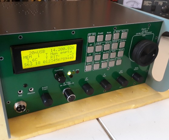
- Ease of use built UI: One function per button keypad for fast and easy operation (No multi-depth menus!).
- Lots of real knobs! Noise blanker for wood-pecker etc, IF Gain & AGC Decay, AF Gain & AF Filter & Notch filter.
- SSB & Full break-in CW, both straight key and paddle (dual contact) keyer.
- Really low noise high performance receiver. (You can put the volume fully up and won’t be deafened by noise. You won’t loose weaker stations in the noise generated inside your rig. Try your rig. Pop on your headphones and turn up the volume on a free frequency…)
- Up to 16 bands. You just fit the parts for the bands you want
- Capable of 16 bands, but initially will be 1.8-54MHZ. The VFO is capable of all LF, HF & VHF bands
- LF and VHF bands (2m) following, VFO and BPF ready now
- Build on 4 PCBs with little inter-board wiring (Mainly ribbon cables)
- An extra data pcb built in provides a USB hub and connection to the processor for CAT, and inbuilt sound card for audio RX and TX connection.
- Function rotary control for adjustment of the function selected by the last button press
- 400 pulse per revolution tuning control, with a a spin and feel in a class of it’s own
- Two Arduino Nano microprocessors and digital readout. The master NANO will upgrade to a NANO EVERY model
- A lot of effort has gone into not compromising the original performance by including digital technology
- Various component footprints are designed for more than one component type to be used. Examples are for the relays, transistors/FETS, SSB filter etc.
- Any extra PCB space has been filled with PTH holes so experiments / enhancements can be fitted on-board. Many component footprints are combined so for instance wired or SMD transistors / FETs can be fitted (eg 3sk51 / BF998)
- Dual memory system built into the software functionality. One for more permanent frequency memories (Memory over power down), and the other for temporary memories say on contest days for fast memory store and delete for working through the band, and quick return to stations not yet worked
- IF Output for external waterfall displays etc
![]()